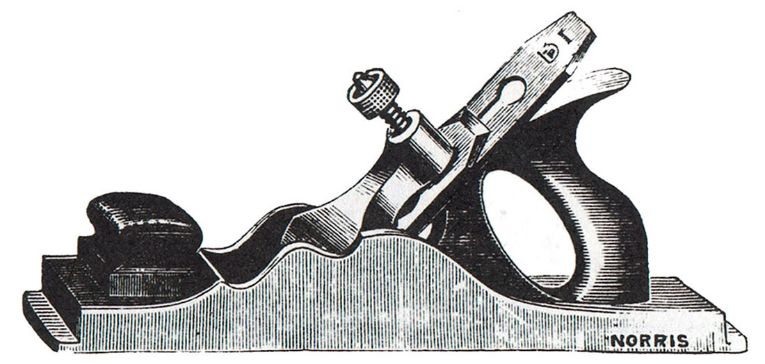
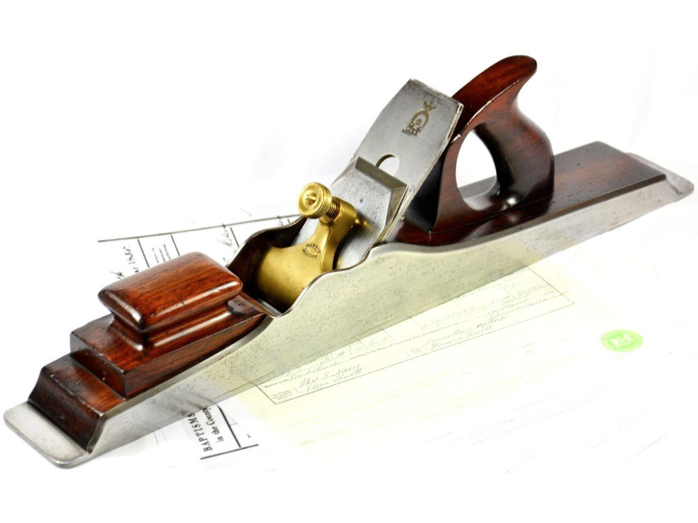
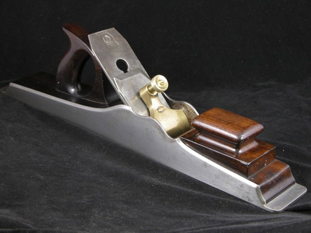
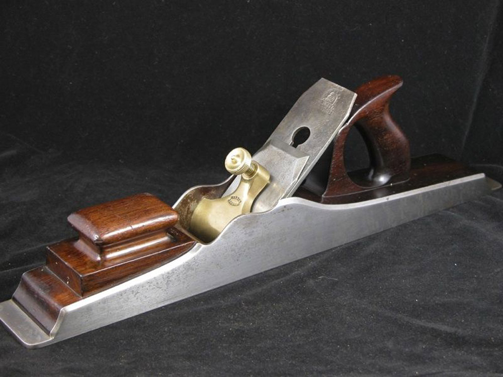
Norris No. 1 Dovetailed Steel Jointing & Panel Plane
as illustrated in the 1914 Norris Catalogue
with 2½ in. Cutters.
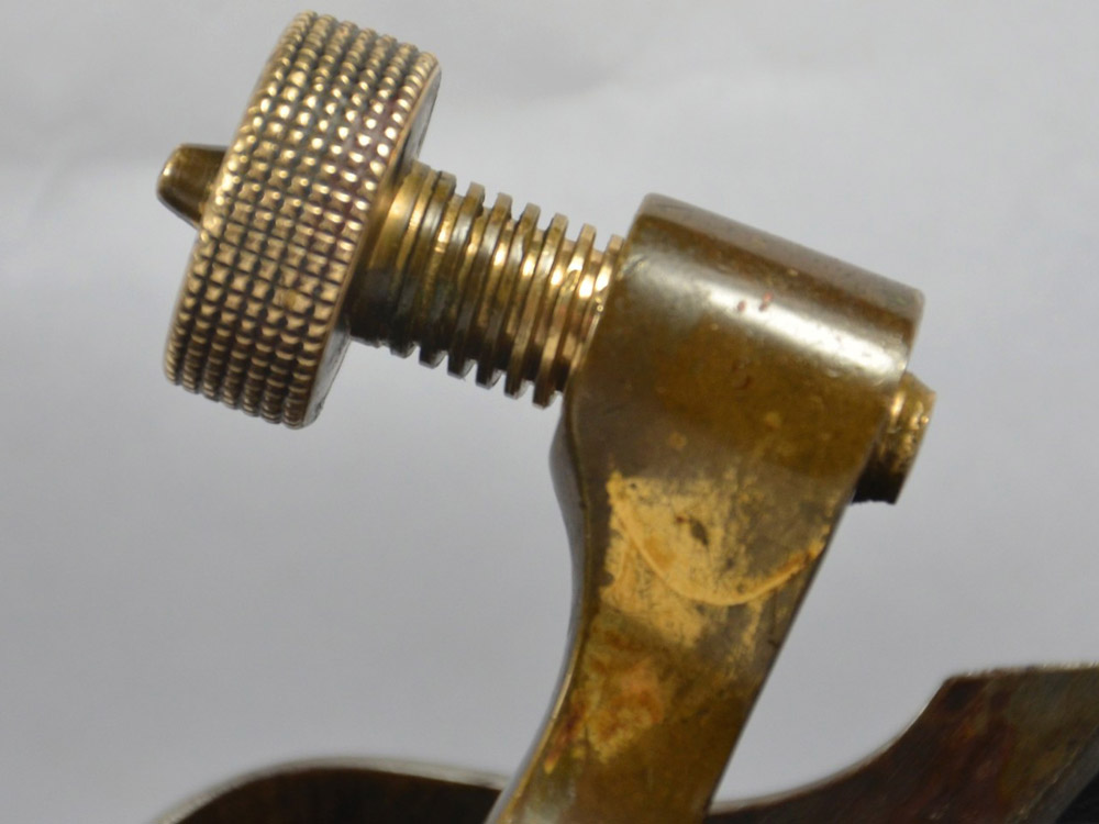
Fitted with rosewood and gunmetal lever.
Broader Irons than 2½ in., 1/- per ⅛ in. extra.
Can be made to 36in. long. Extra Cutters to fit above planes, 2/- each.
| Panel Planes: Length | 11½” | 12½” | 13½” | 14½” | 15½” | 16½” | 17½” |
|---|---|---|---|---|---|---|---|
| Price (1908 Price List) | 30/- | 30/- | 30/- | 31/- | 32/- | 33/- | 34/- |
| Price (1914 Catalogue) | — | — | 30/6 | 31/6 | 32/6 | 33/6 | 34/6 |
| Price (1928 Catalogue) | — | — | 60/- | 62/- | 64/- | 66/- | 68/- |
![]()
| Jointing Planes: Length | 20½” | 21½” | 22½” | 23½” | 24½” |
|---|---|---|---|---|---|
| Price (1908 Price List) | 35/6 | 36/6 | 37/6 | 38/6 | 39/6 |
| Price (1914 Catalogue) | 36/6 | — | 37/6 | — | 40/6 |
| Price (1928 Catalogue) | 72/- | — | 75/- | — | — |
![]()
| Jointing Planes: Length (Cont.) | 25½” | 26½” | 27½” | 28½” |
|---|---|---|---|---|
| Price (1908 Price List) | 40/6 | 42/6 | 44/6 | — |
| Price (1914 Catalogue) | — | 43/6 | — | 46/6 |
| Price (1928 Catalogue) | 85/- | — | — | 95/- |
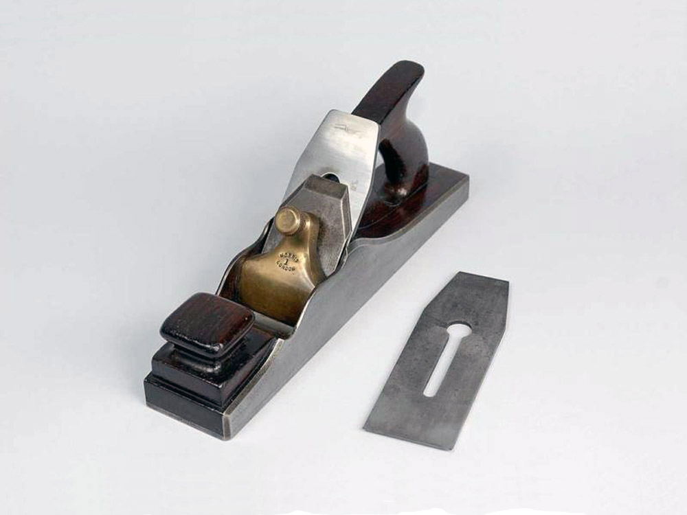
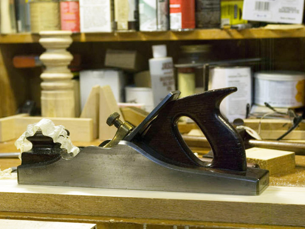
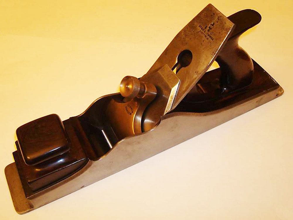
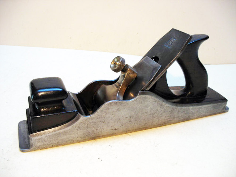
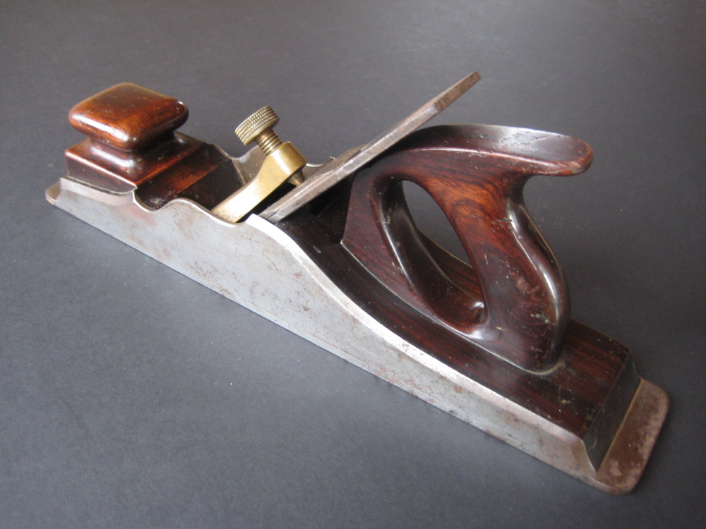
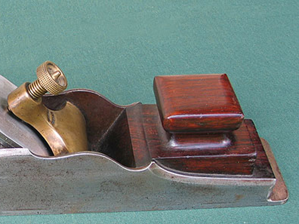
NOTES: The No. 1 encompasses a large range of sizes and, for this reason, I have broken them into Panel planes and Jointing planes (above) depending on the length.
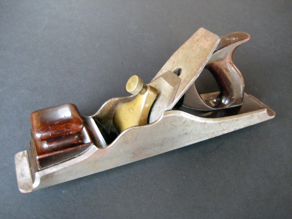
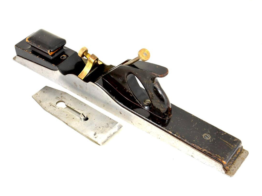
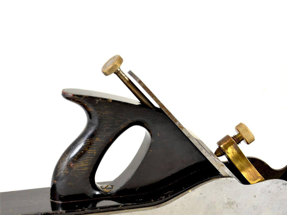
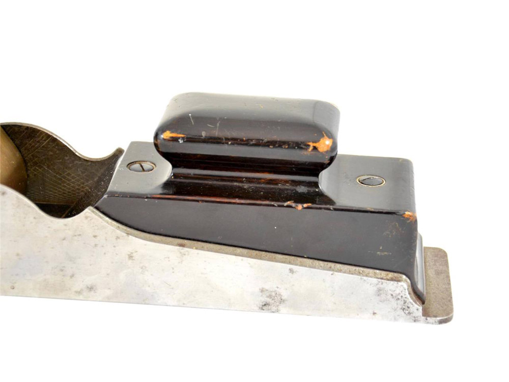
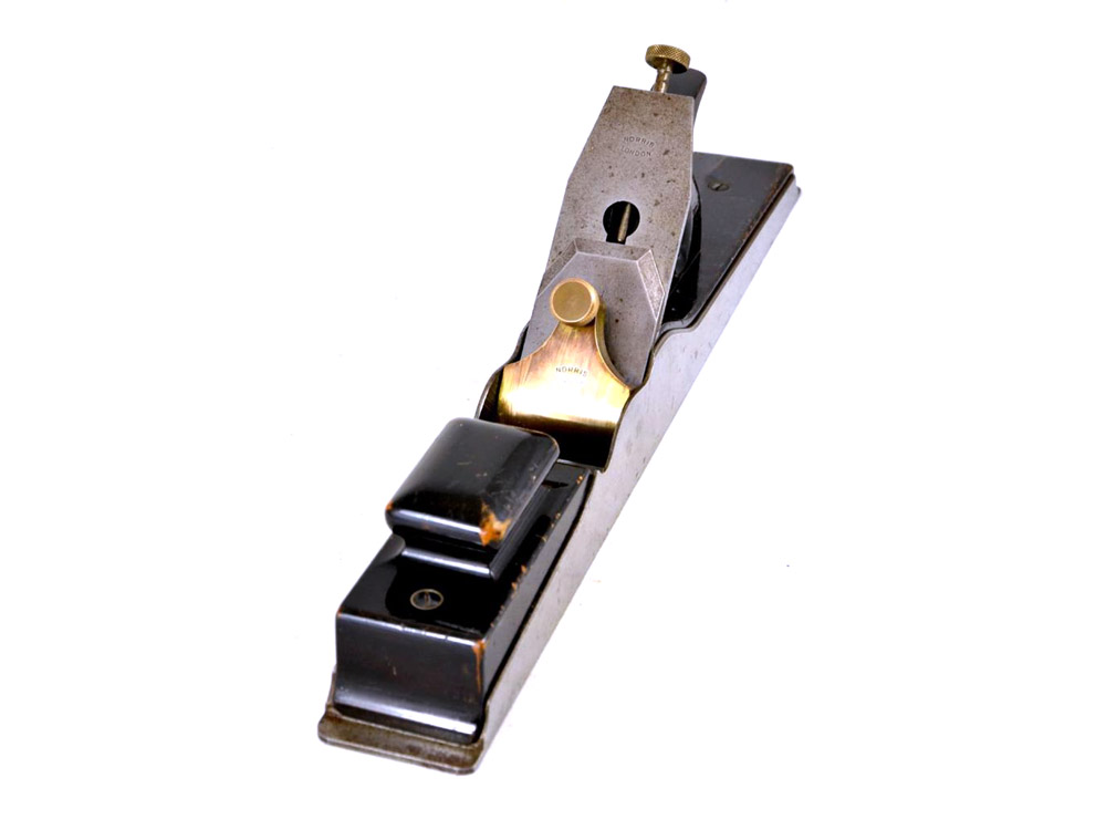
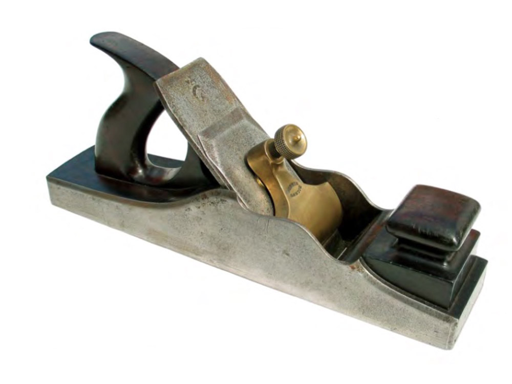
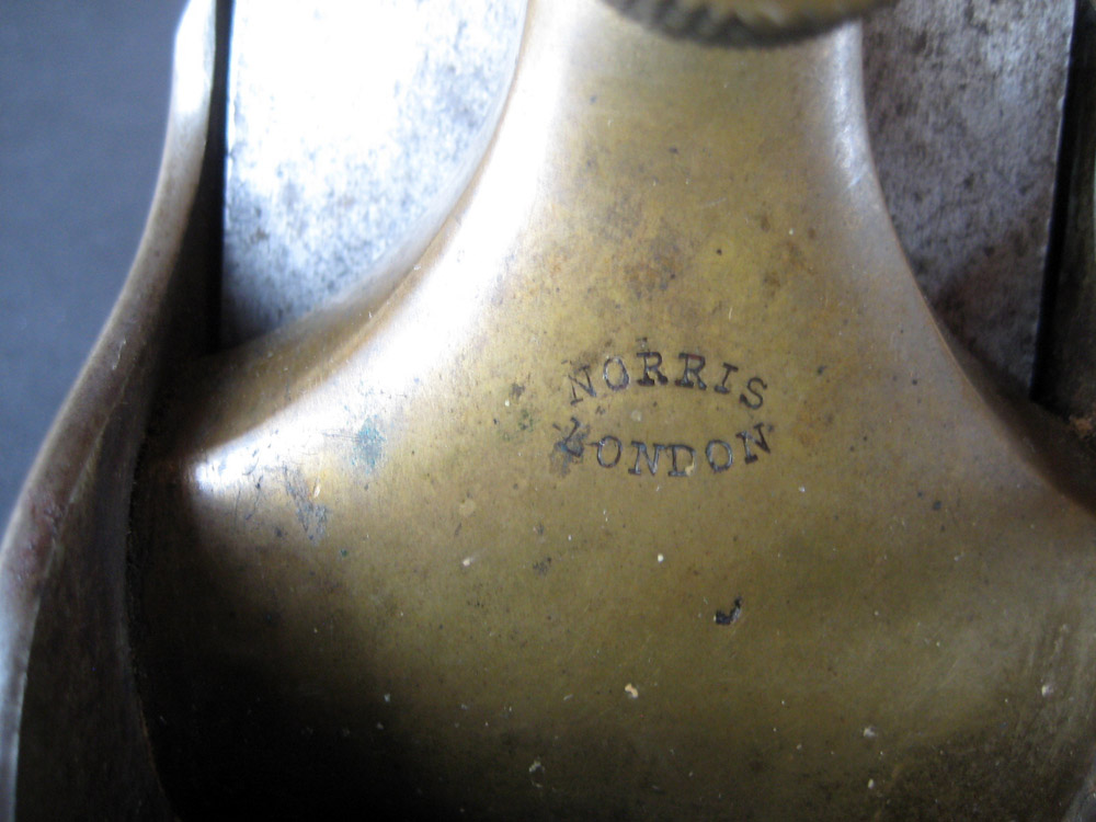
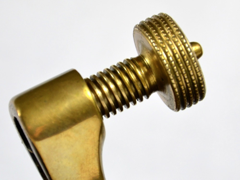
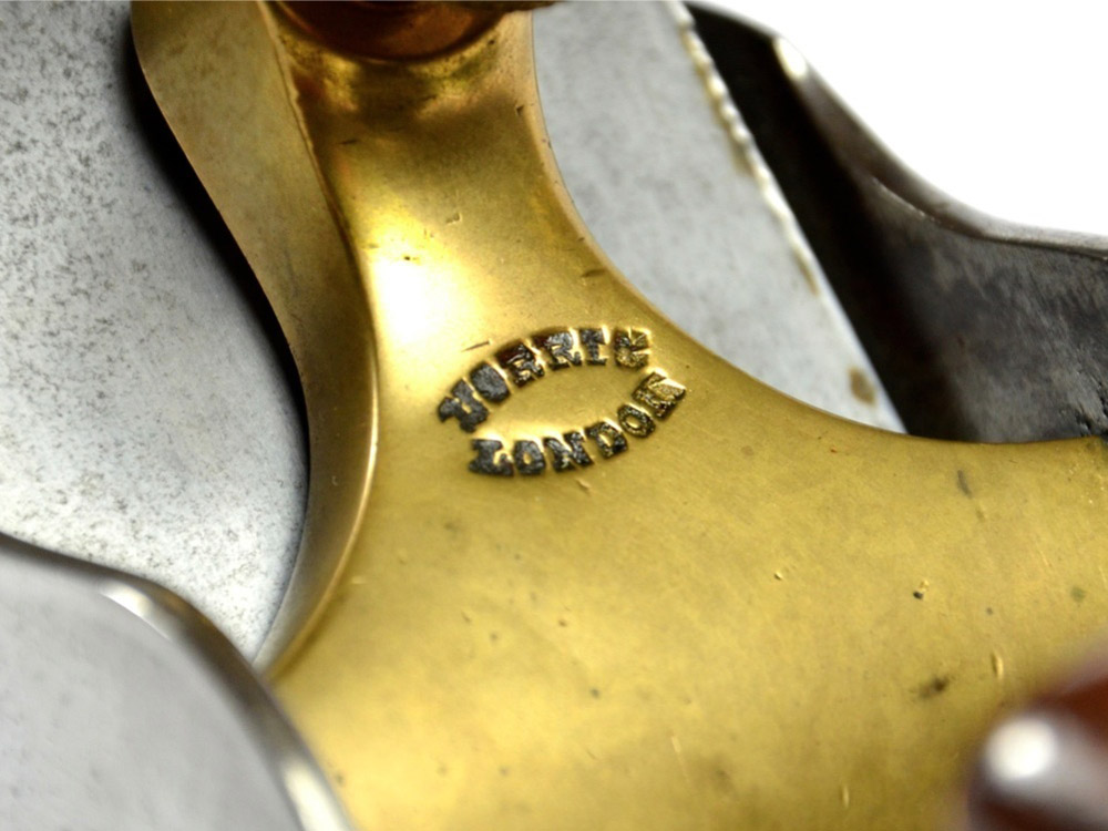
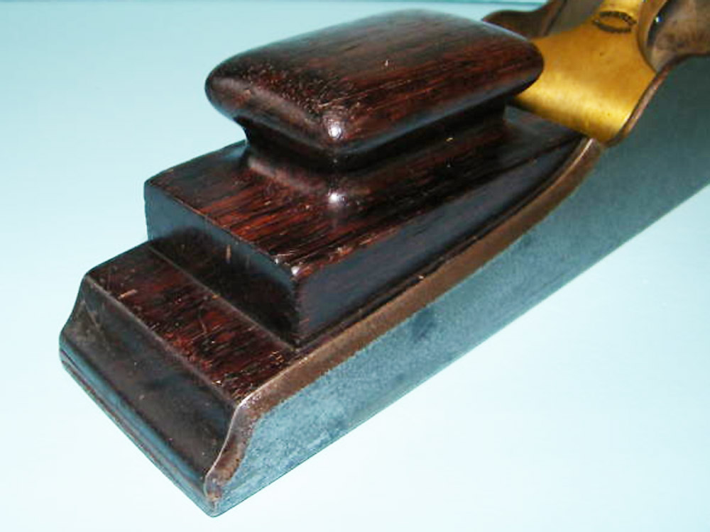
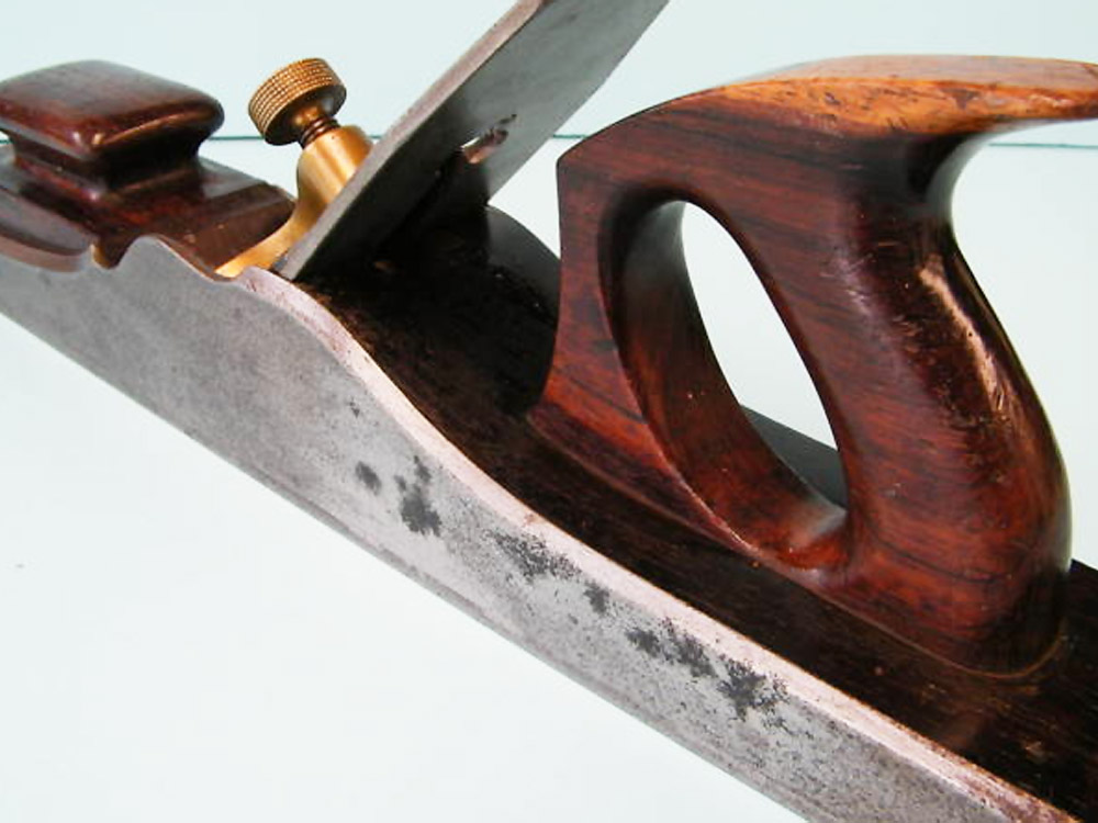
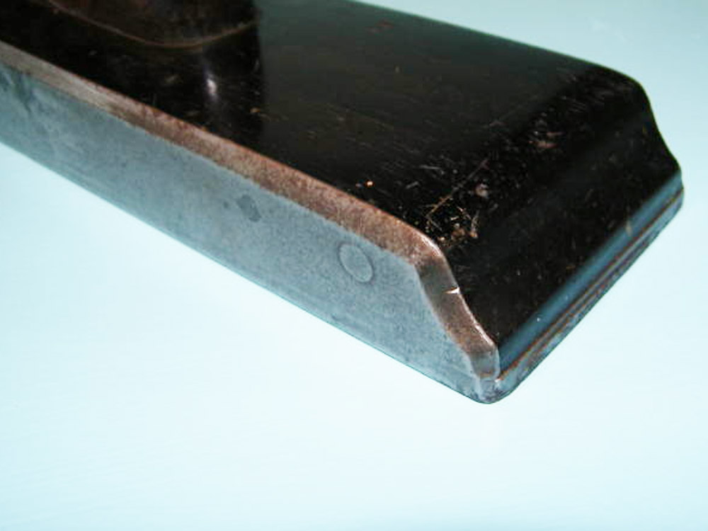
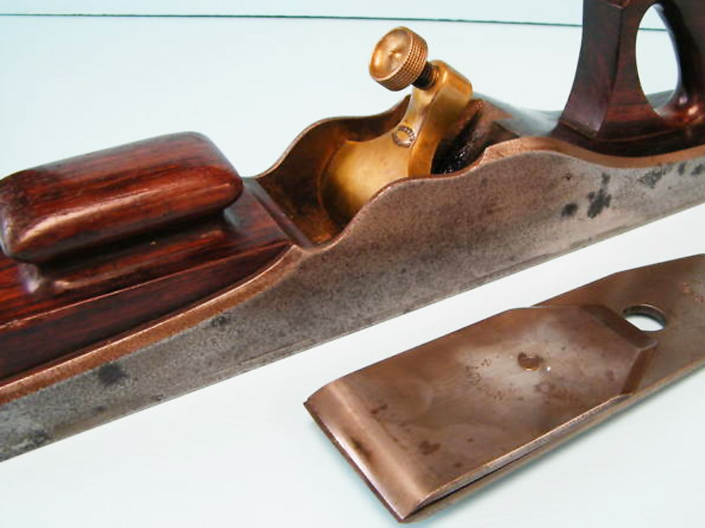
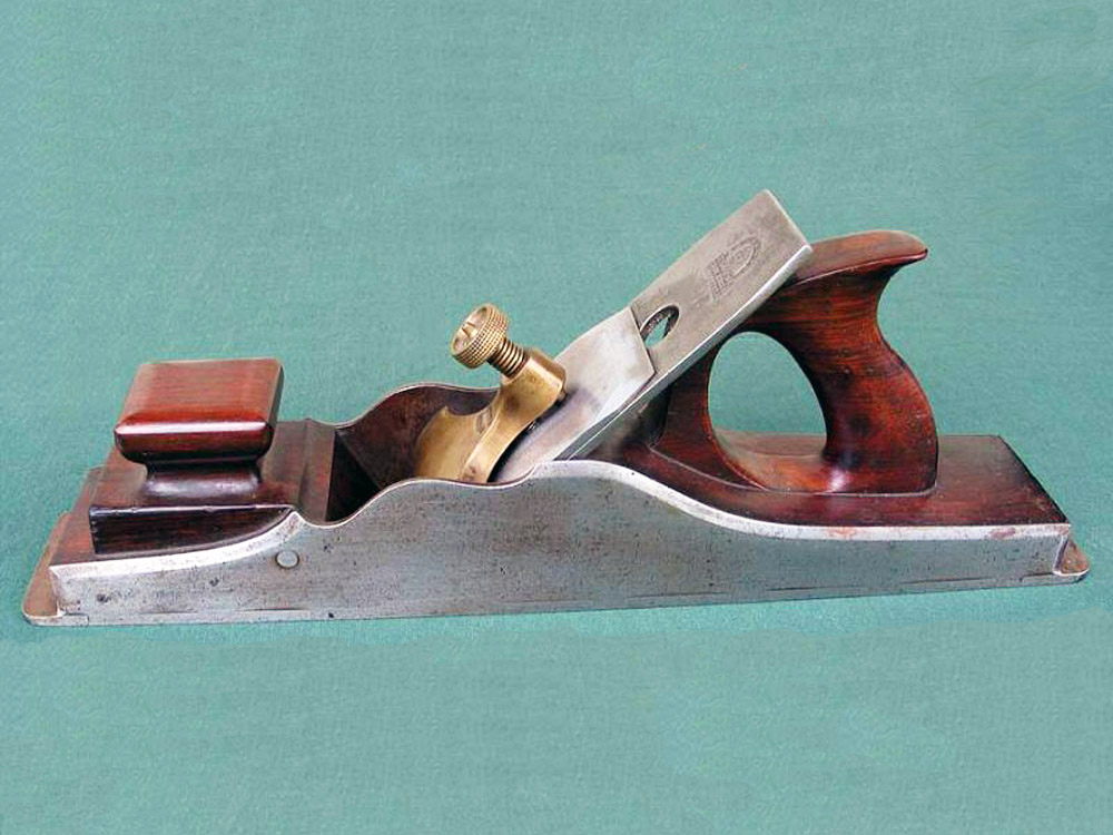
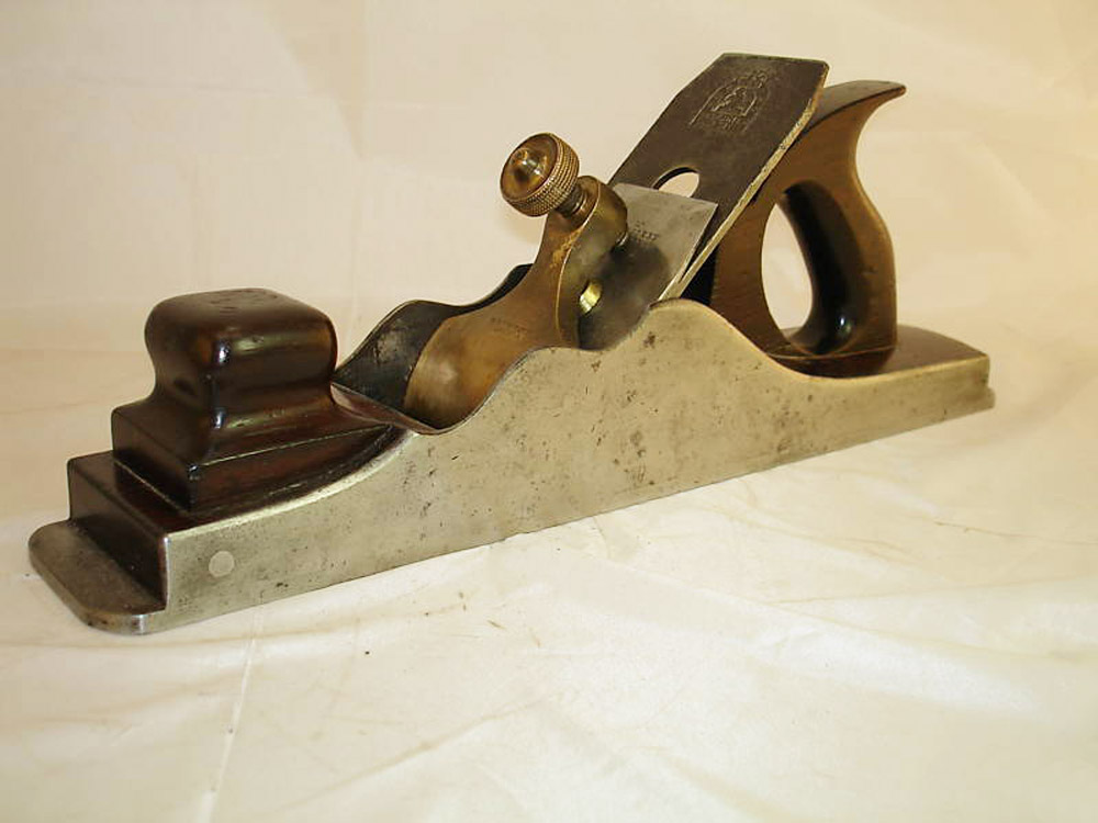
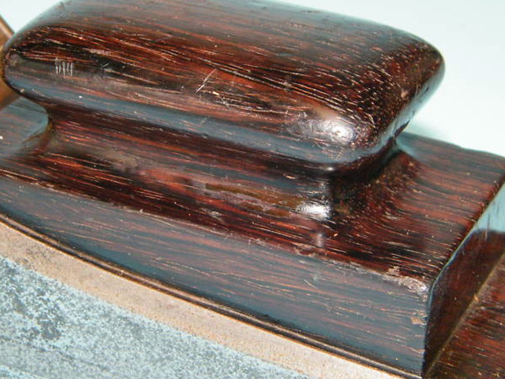
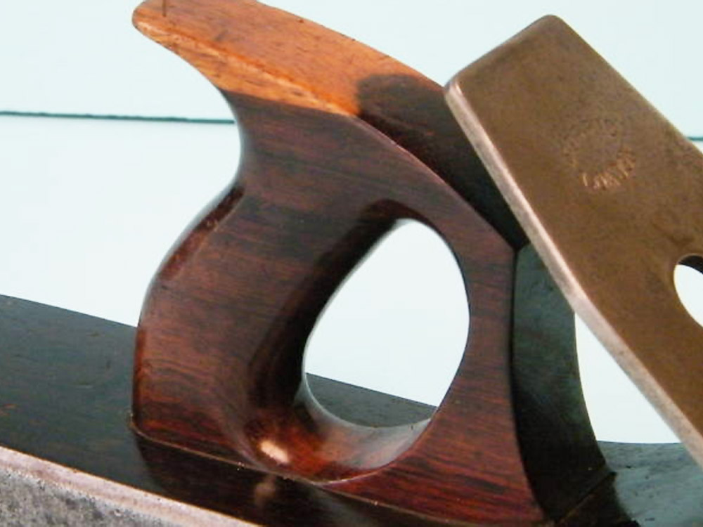
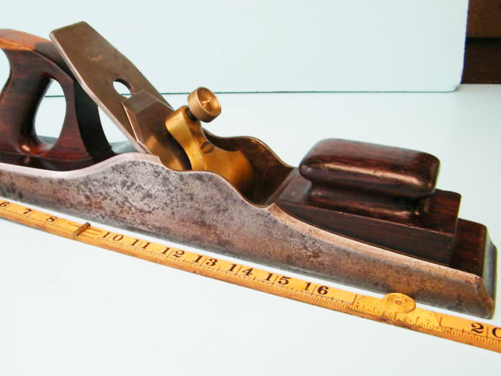
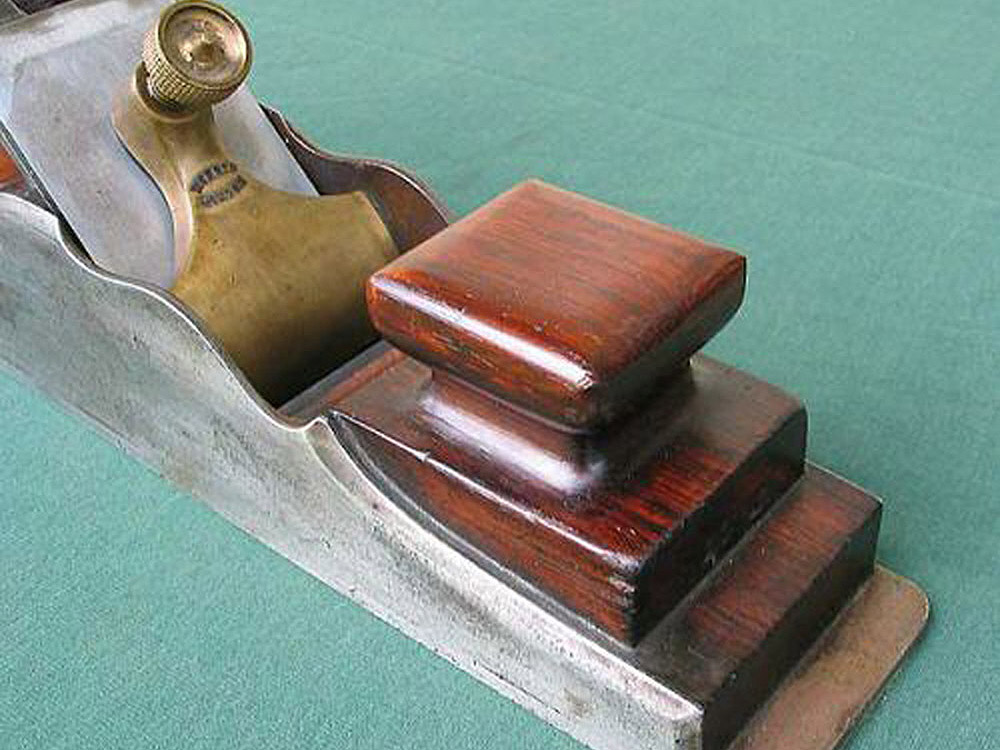
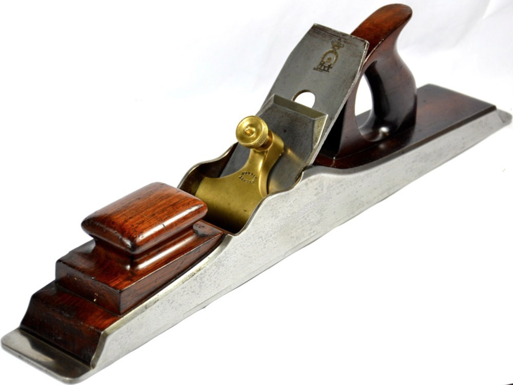
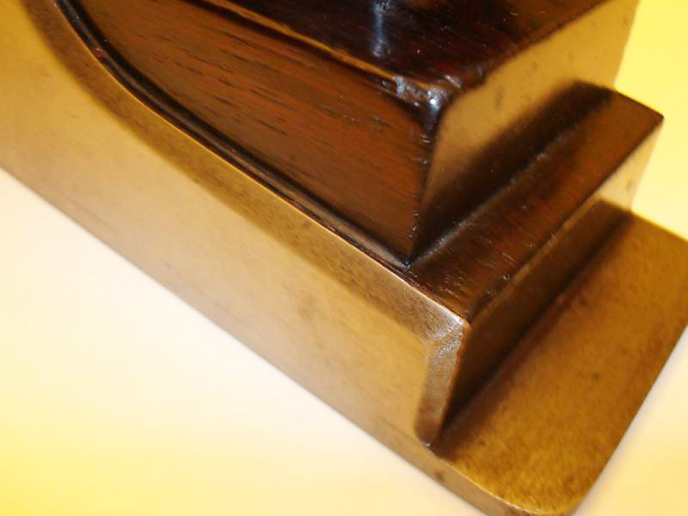
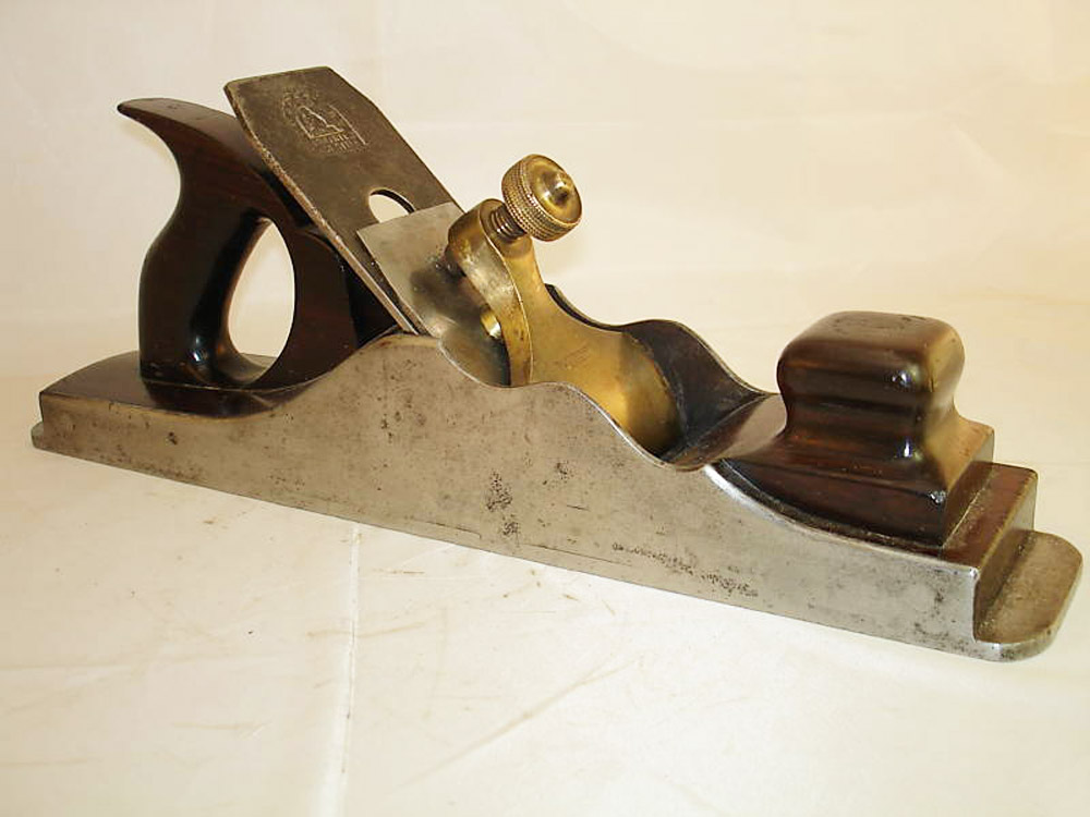
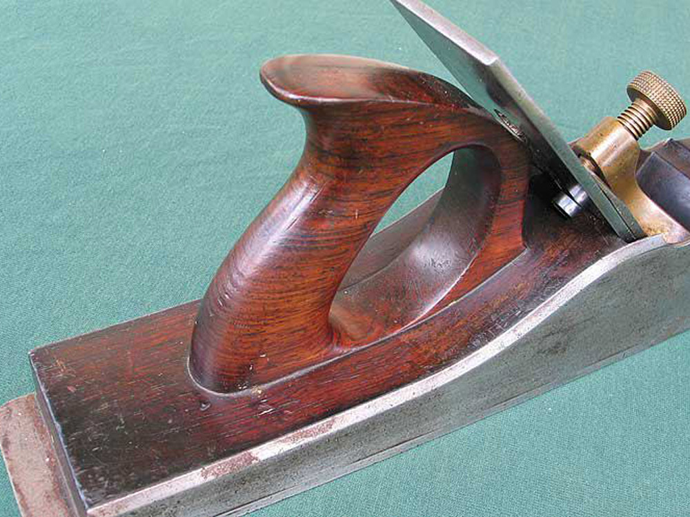
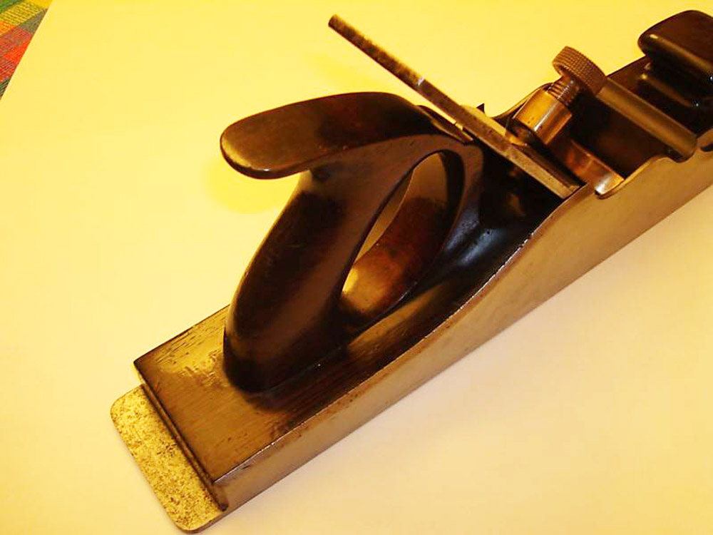
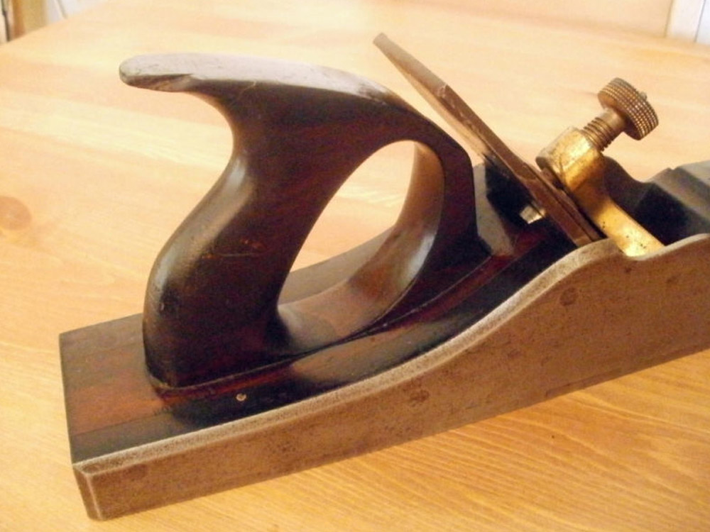
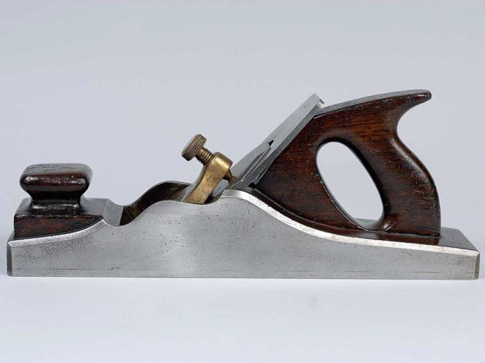
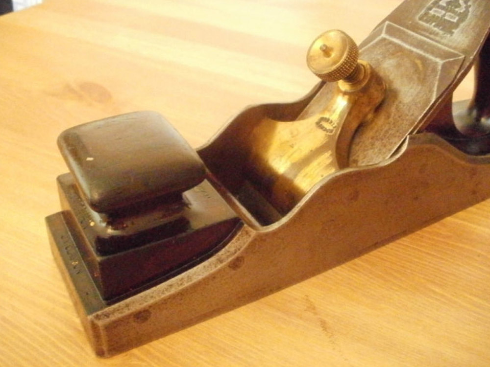
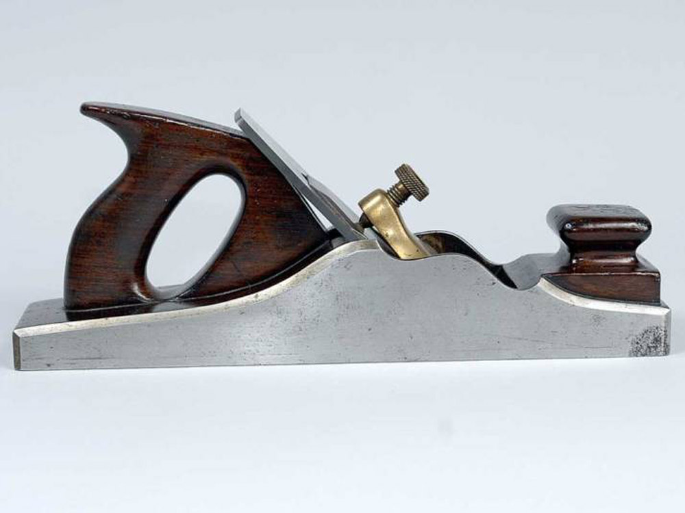
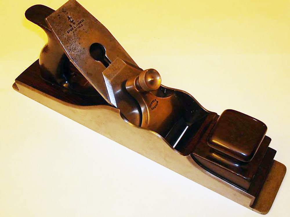
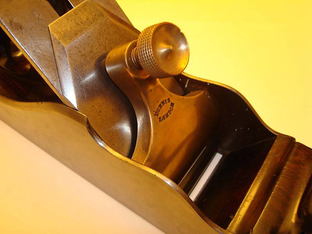
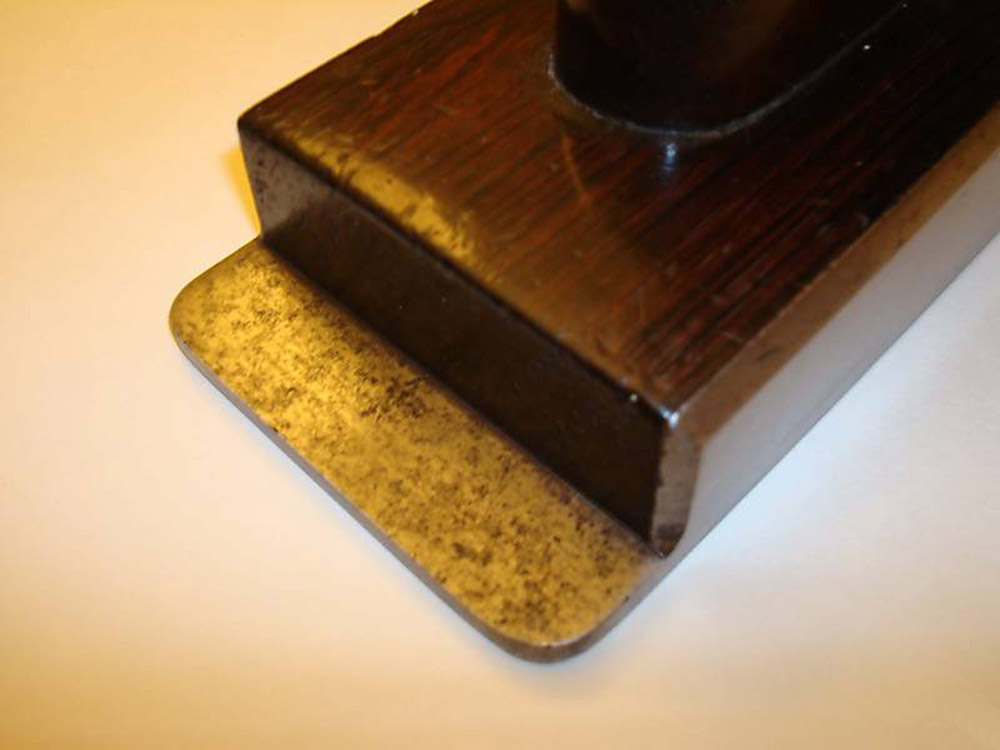
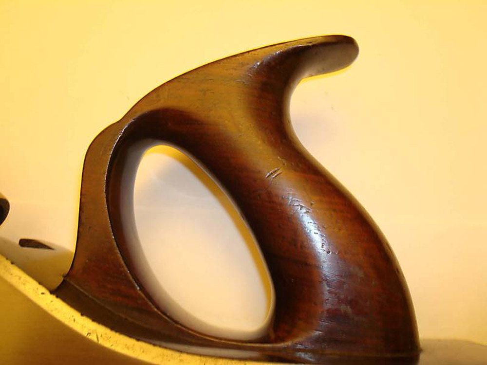
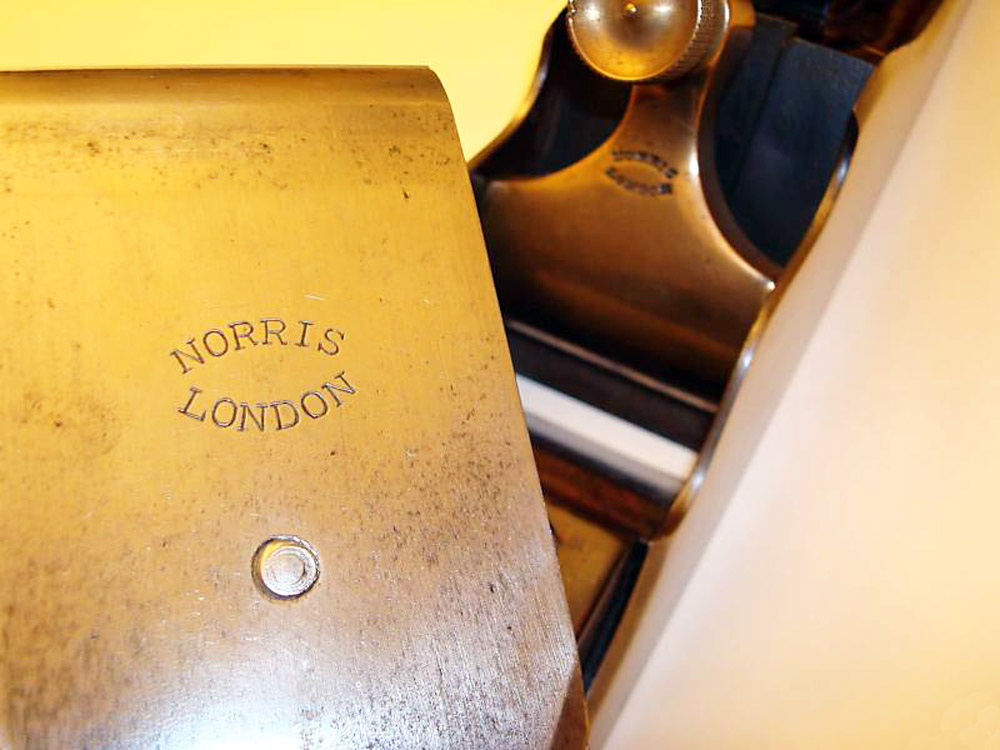
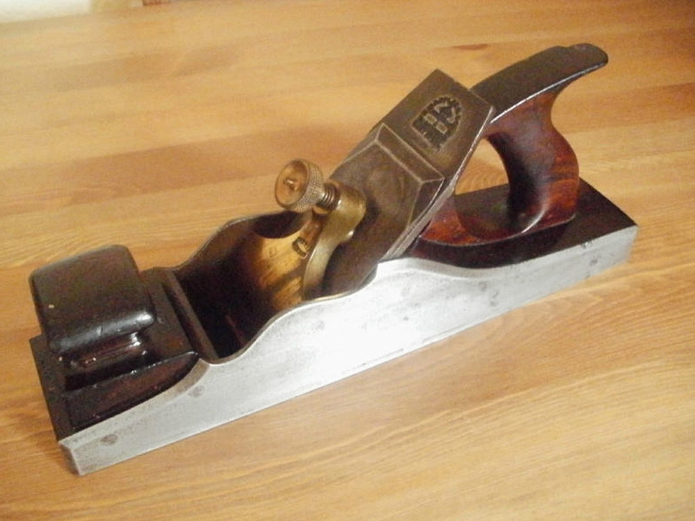
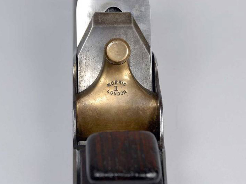
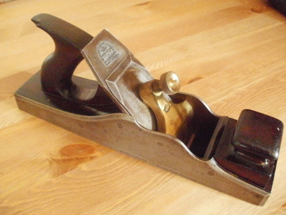
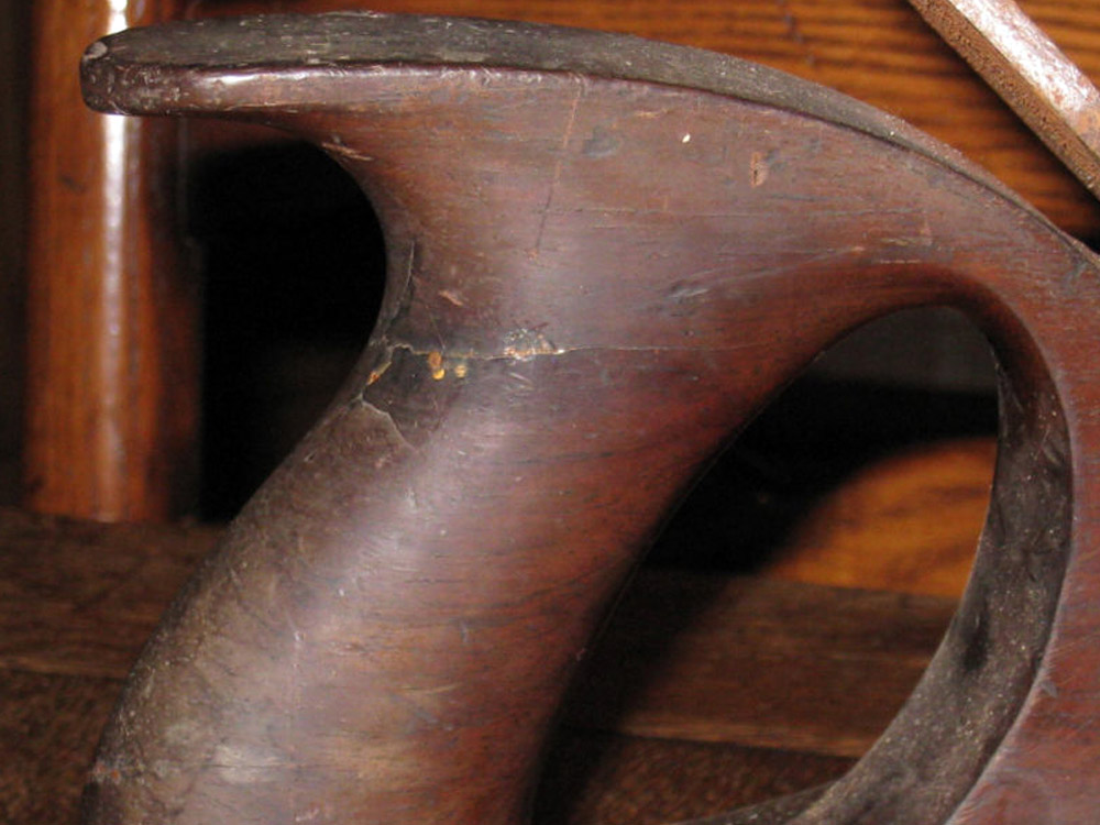
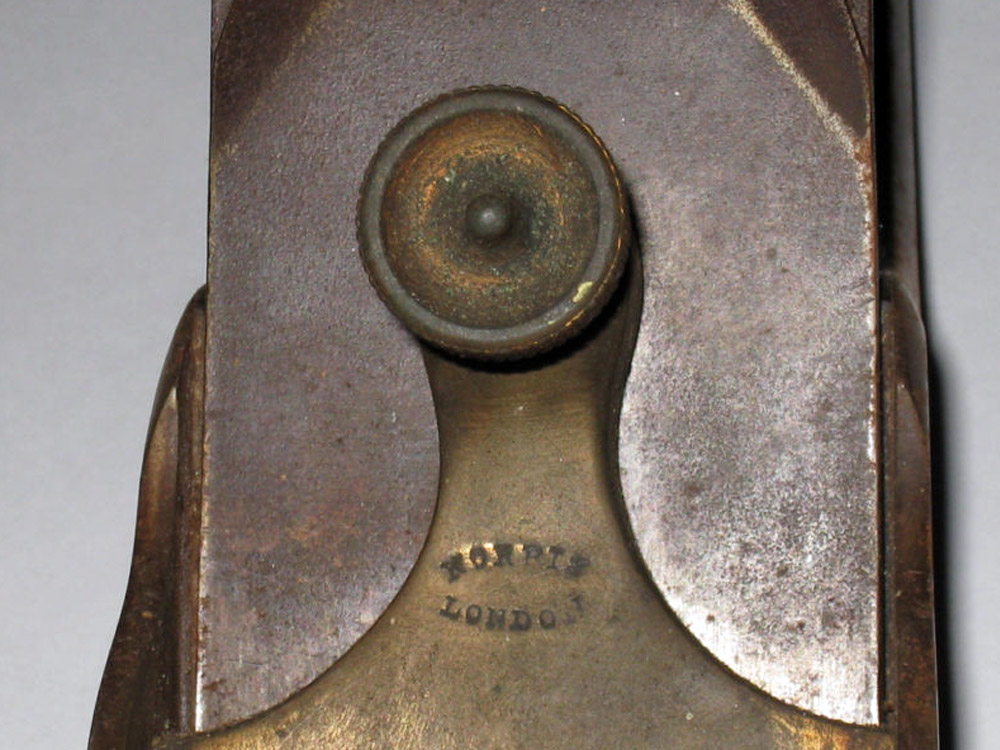
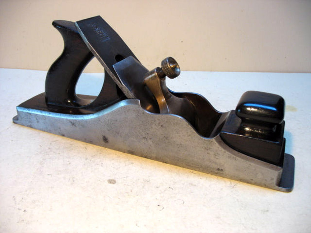
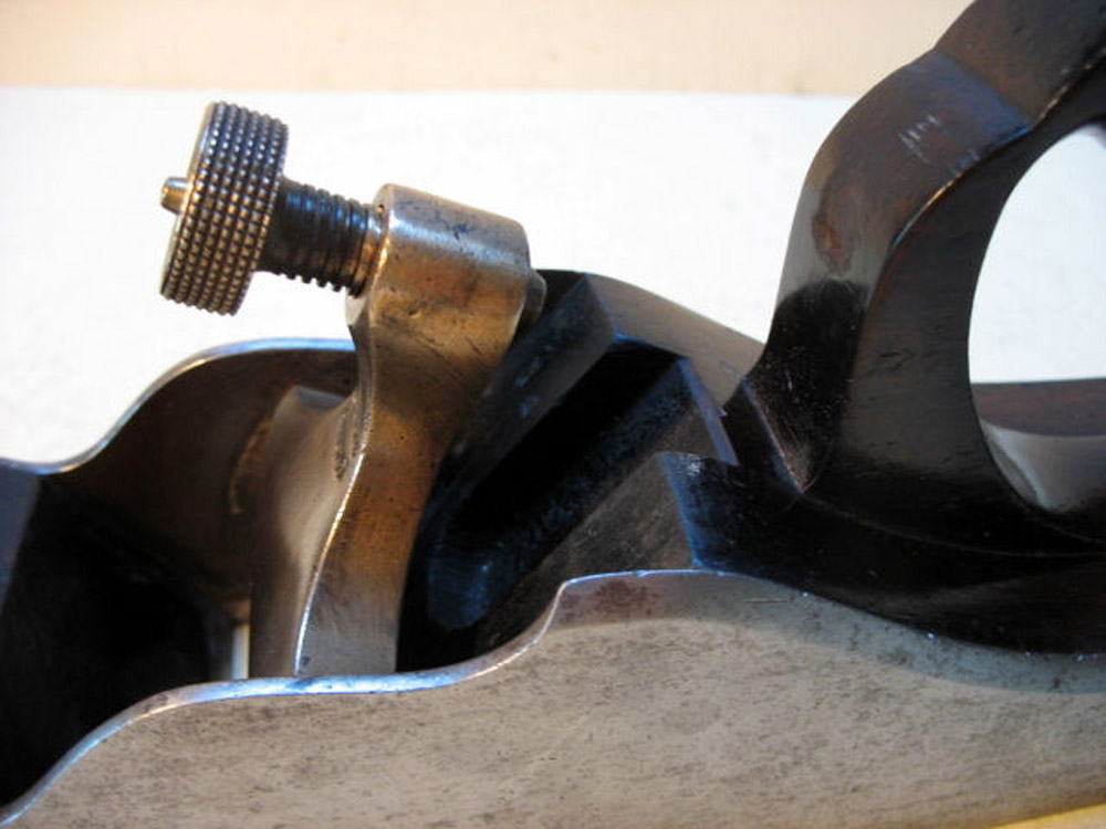
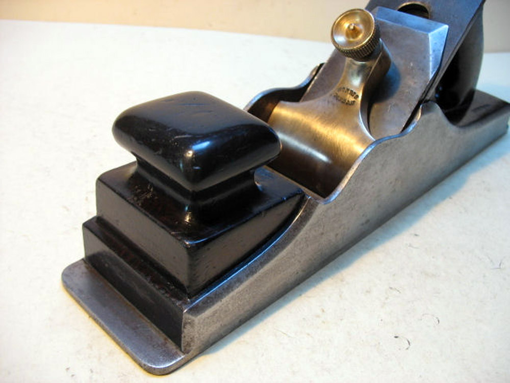
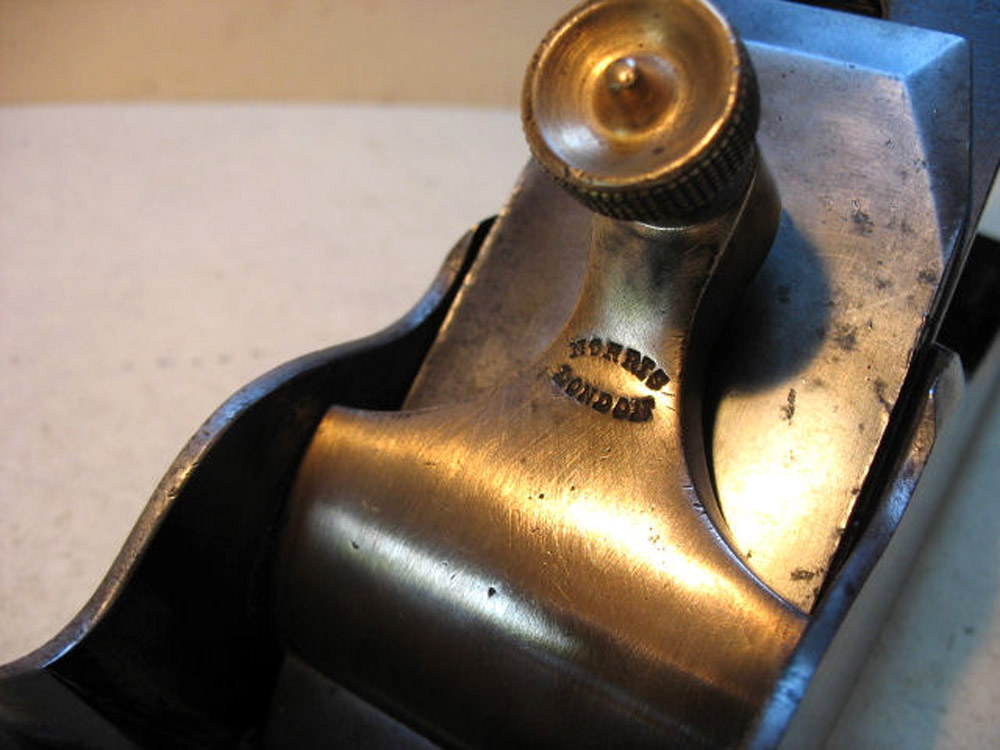
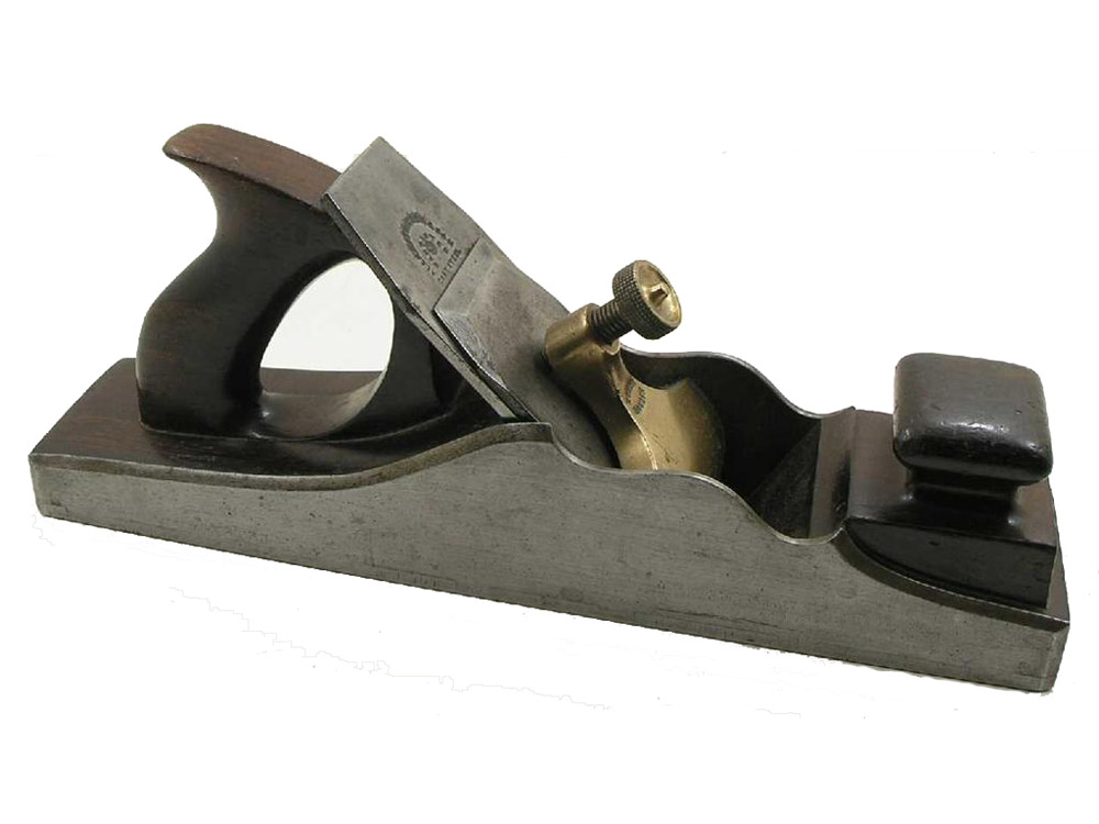
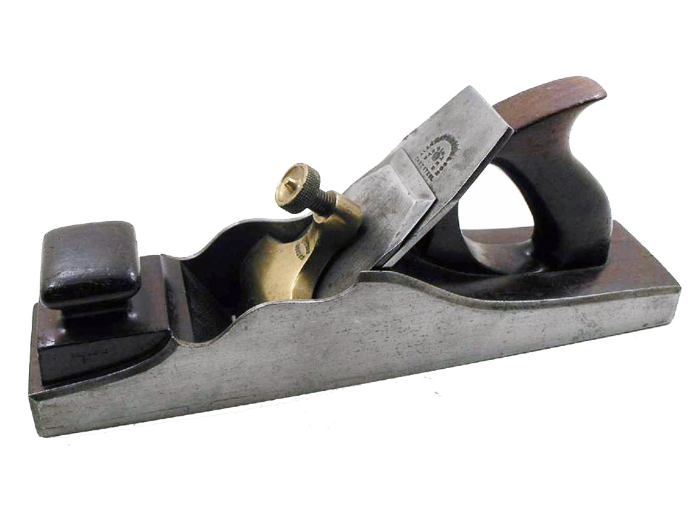
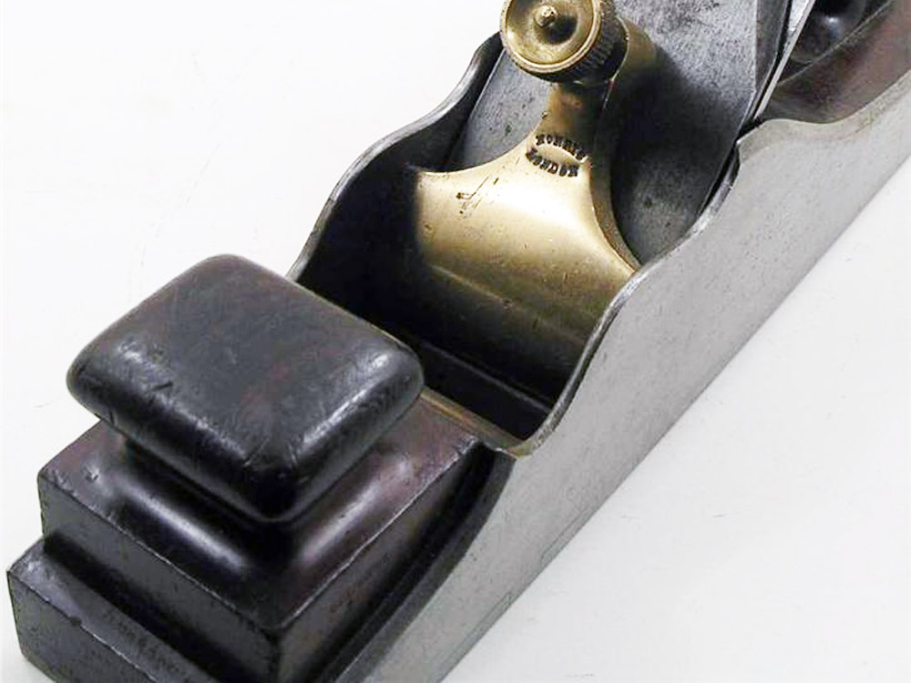
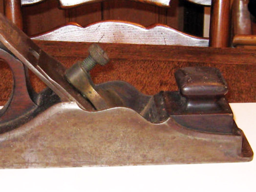
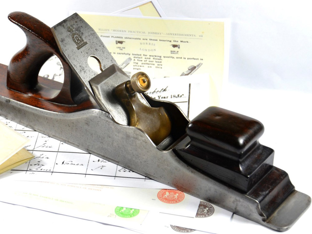
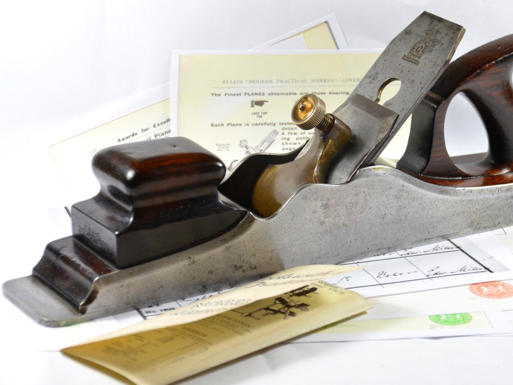
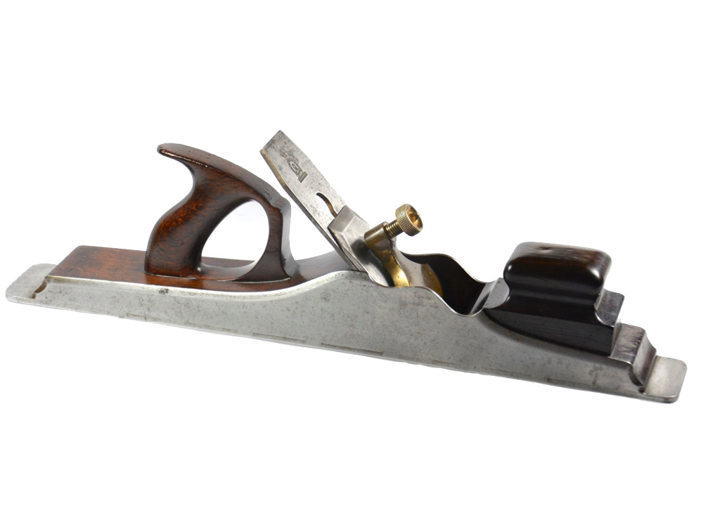
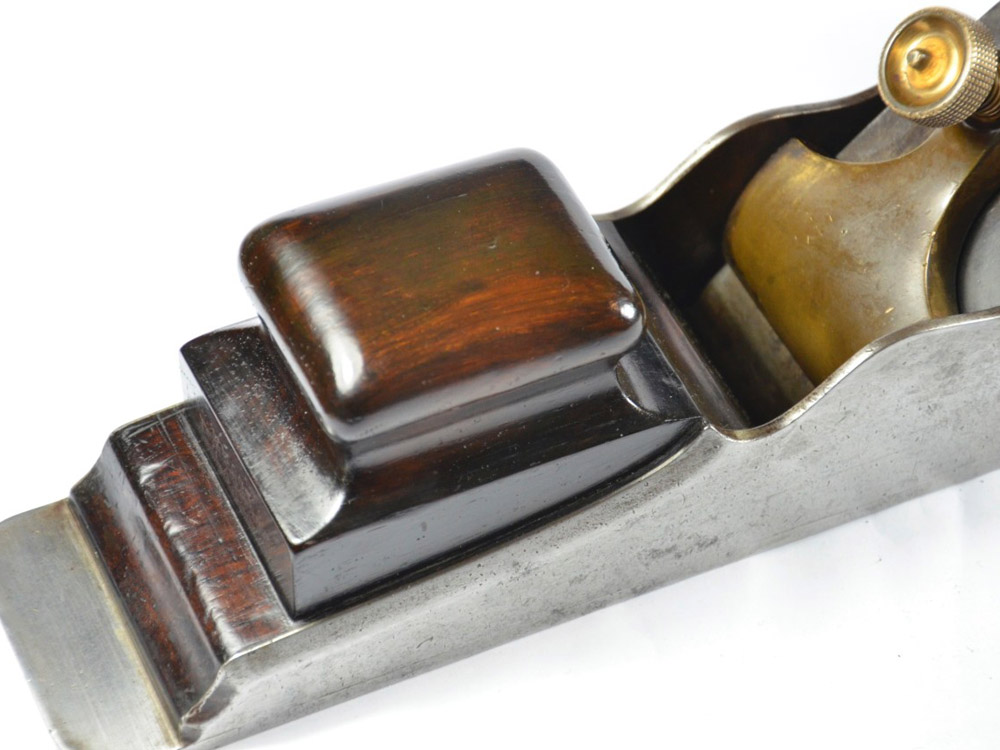
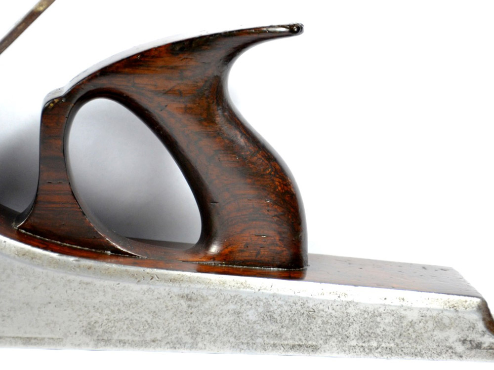
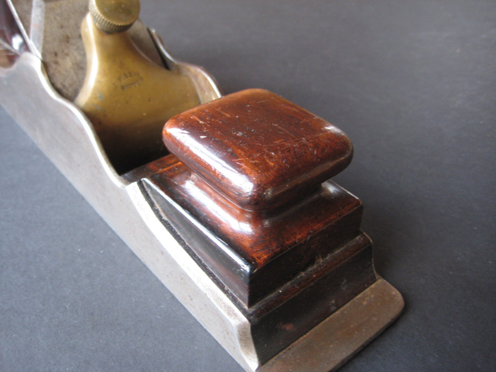
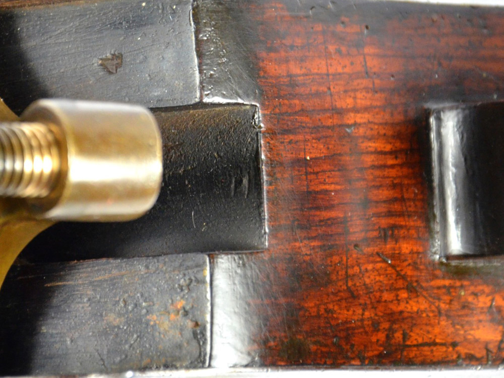
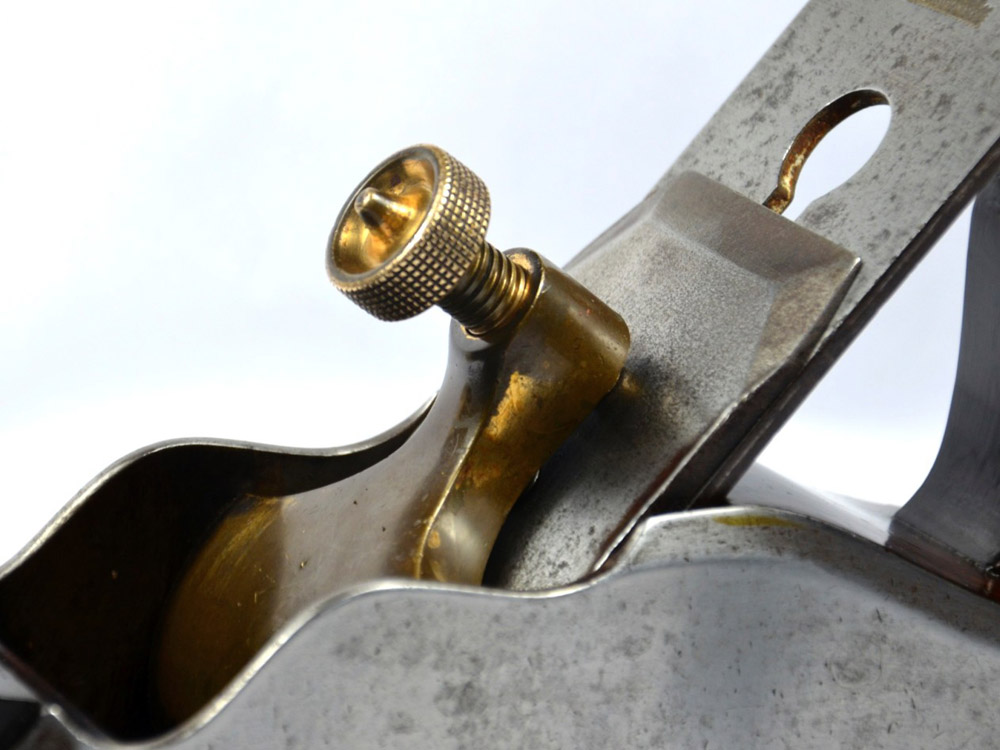
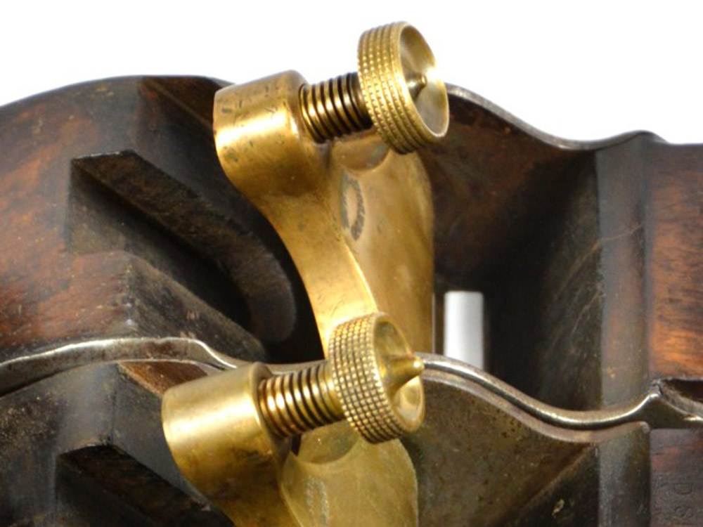
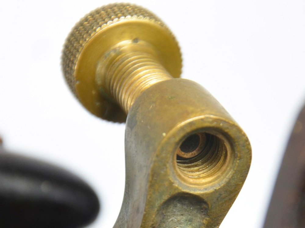
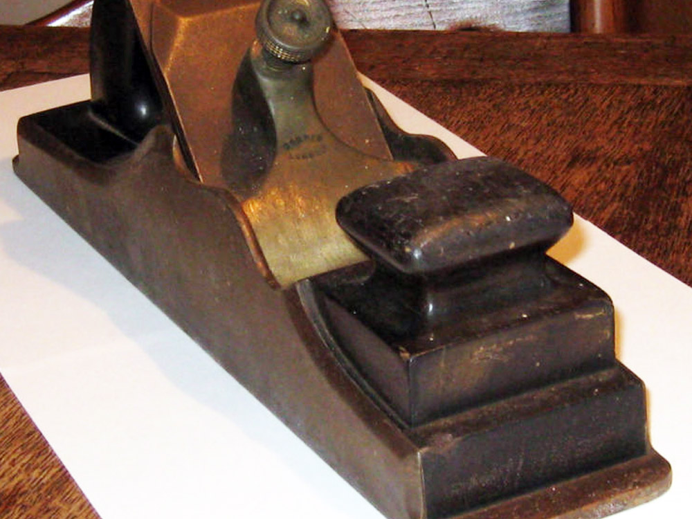
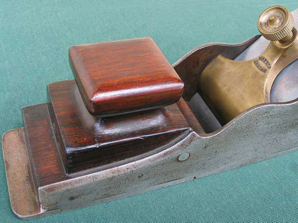
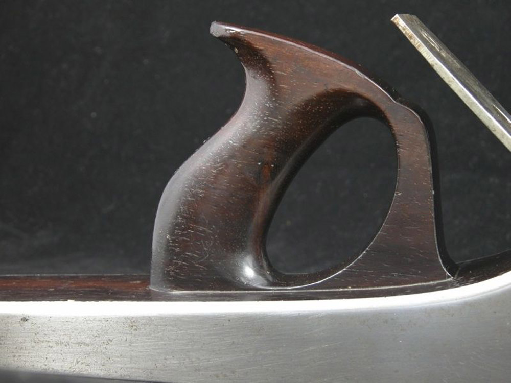
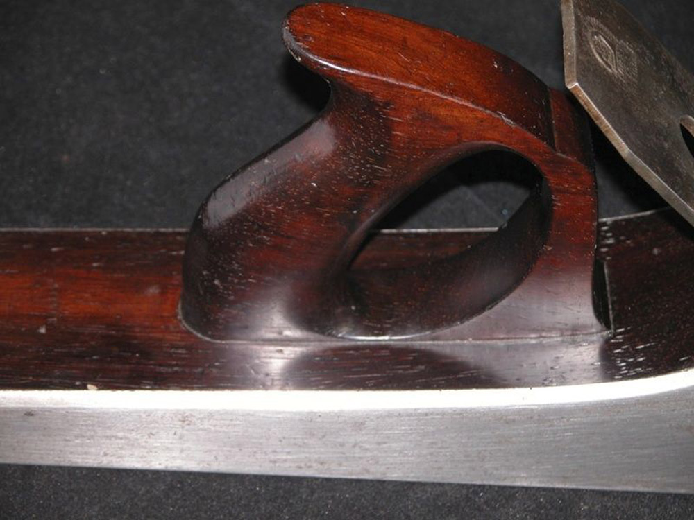
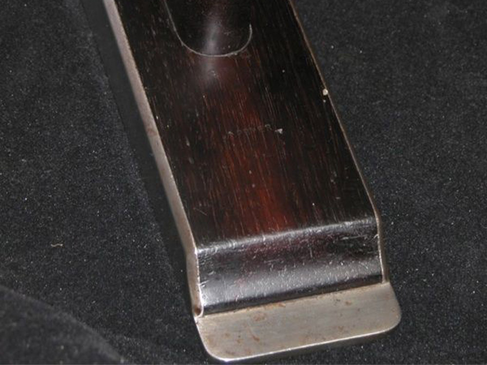
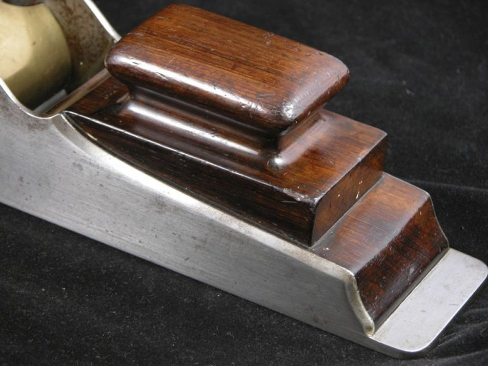
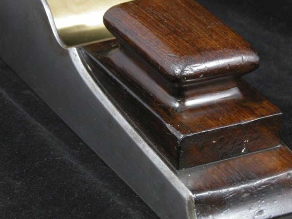
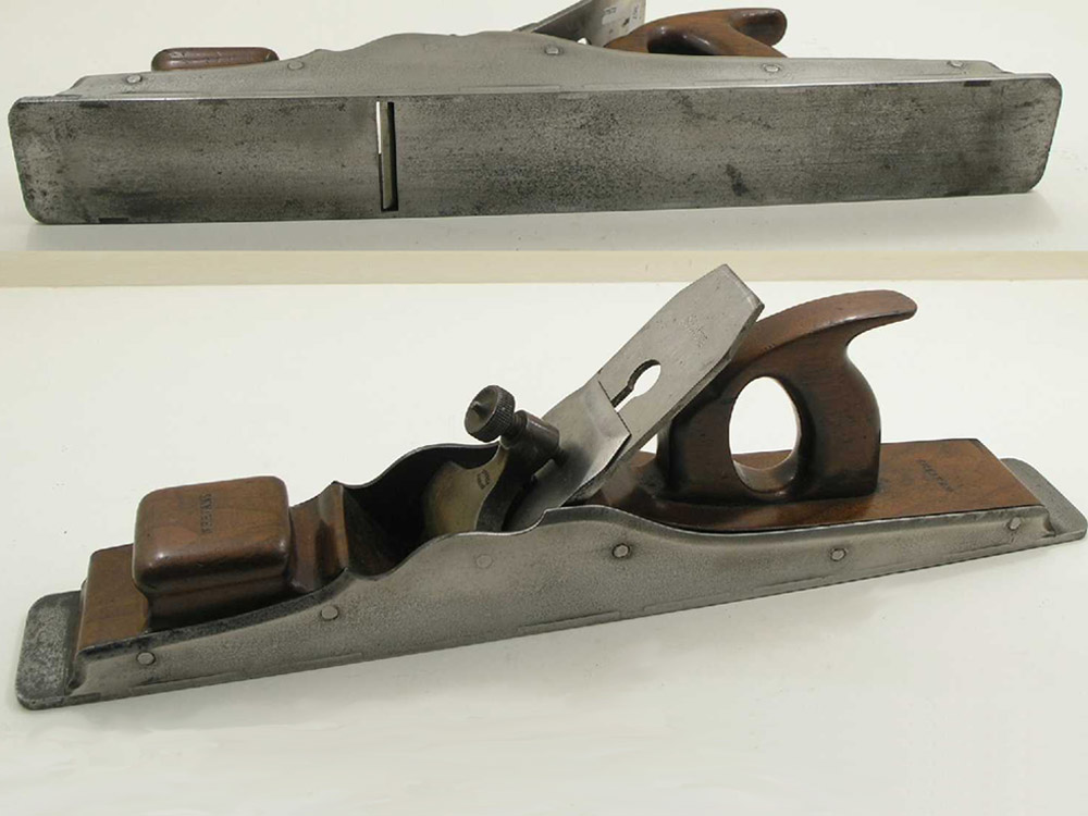
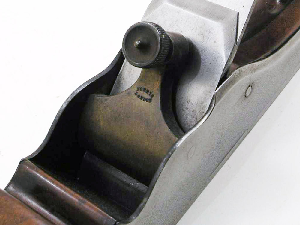
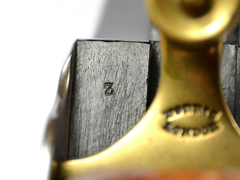
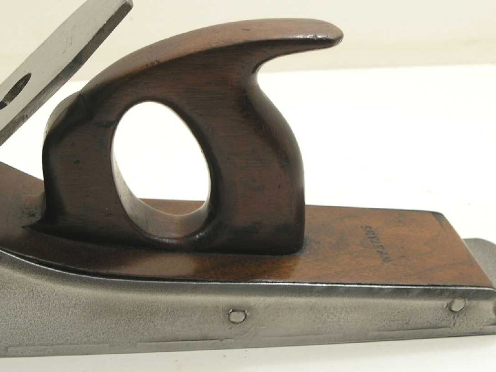
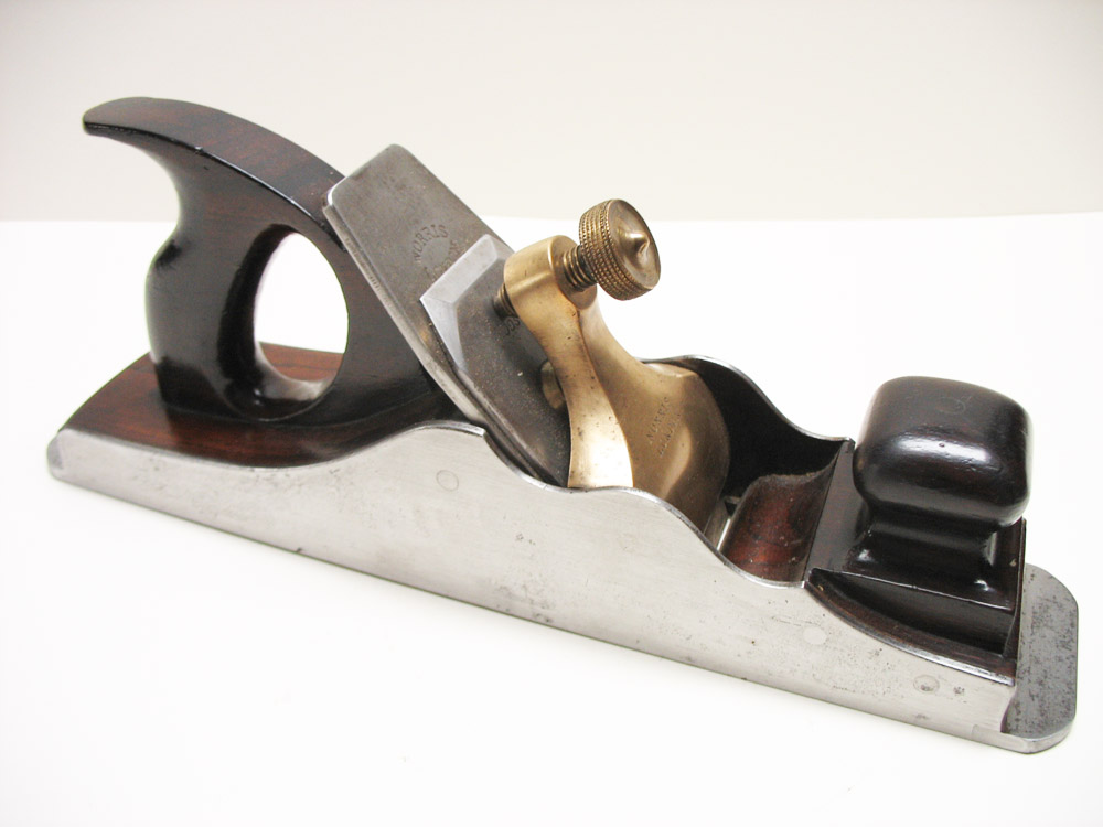
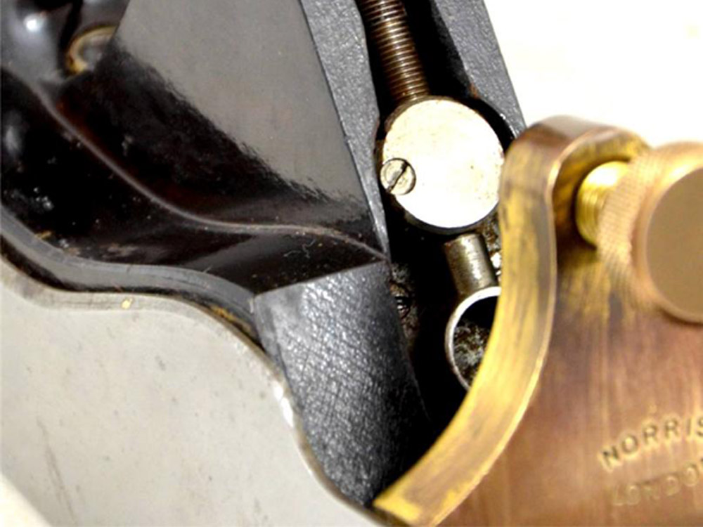
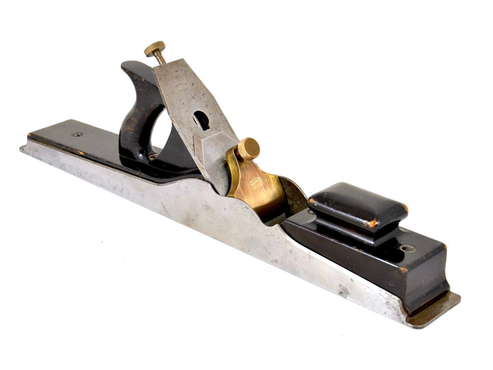
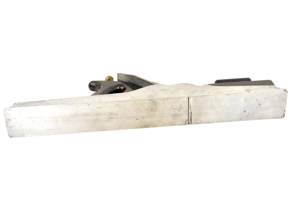
Both types of planes are very similar in appearance, as can be seen in the catalogue engraving above and the accompanying images below. Both have the characteristic front bun, which is cushion-shaped to provide a comfortable grip for the hand — though the bun on the jointing planes are elongated, rather than square, to reflect the length of the plane. The longer planes, both panel and jointing, also have projecting soles at the toe (front) and the heel (rear) of the plane. Some early planes had wedged irons, and came with a gunmetal bridge to hold the wedge and cutting iron in place. Most planes, however, used a gunmetal levercap and screw to hold the iron. Both wedged and levercap models were stamped with the “NORRIS / LONDON” mark on the bridge or levercap.
As far as the design, materials and construction of the Norris No. 1 is concerned they’re not exactly original. The side profiles follow, almost exactly, the designs set out by Stewart Spiers for his Panel and Jointing planes. Not the really early Spiers planes, but the models from about the 1870’s onwards — also referred to as the “Type 3’s”. Of course Norris was not alone in the adoption of these designs, as Mathieson, Preston, Marples and other makers were also using them, causing Spiers to remark on the many “imitations now before the public” in their various catalogues.
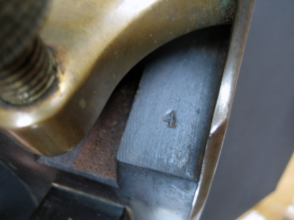
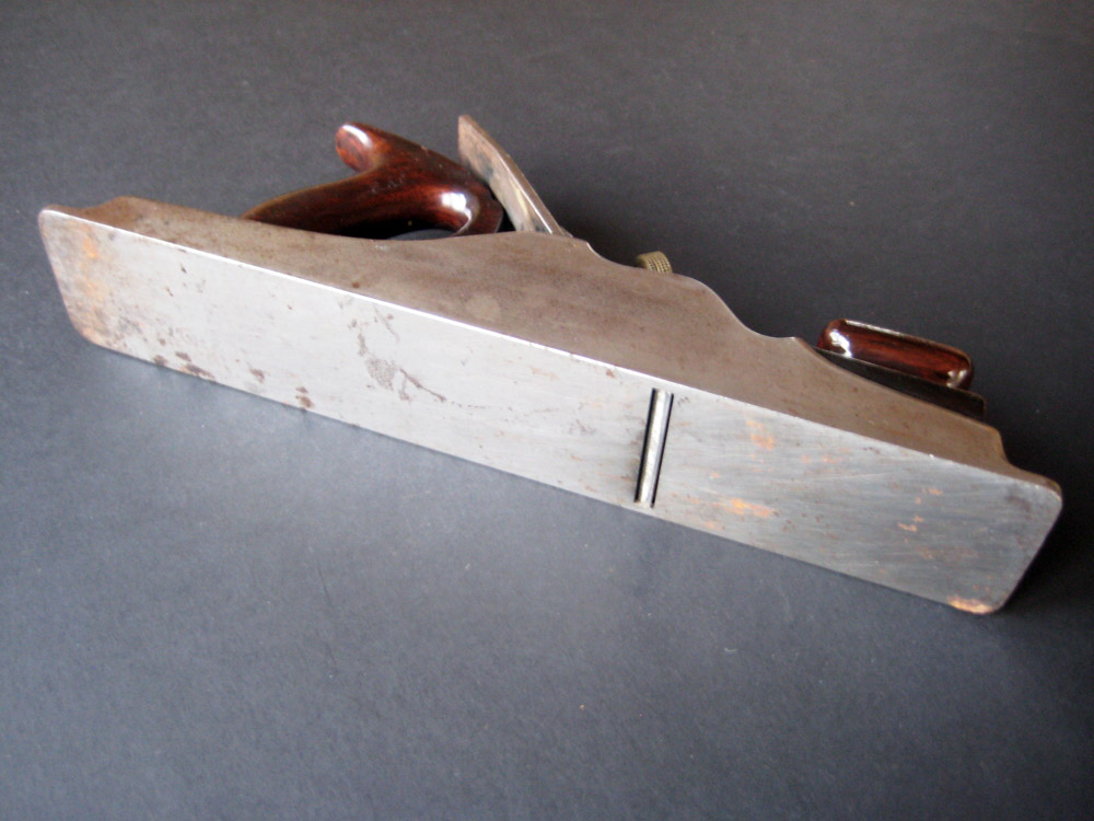
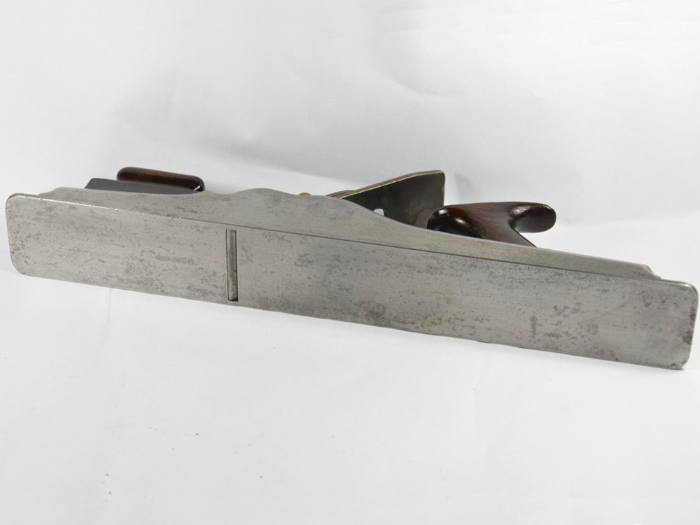
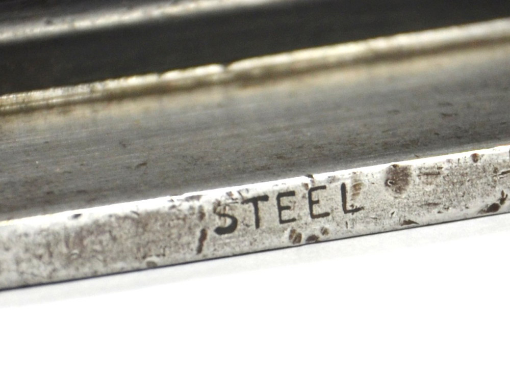
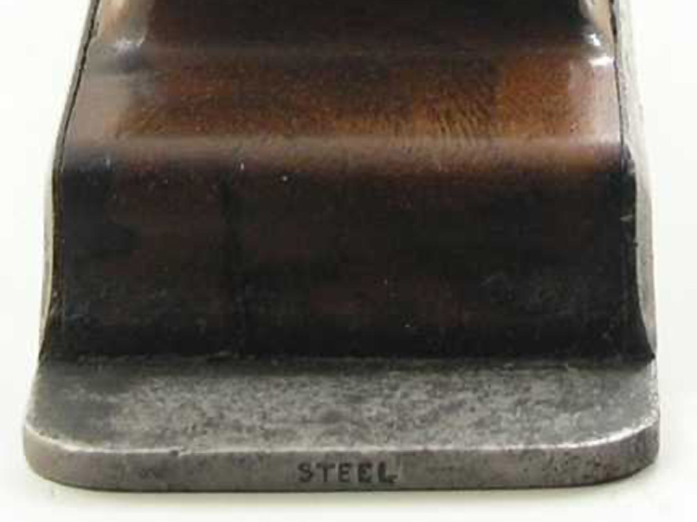
The body of the No. 1 was made from mild steel plates which are dovetailed together to form a very strong, interlocking joint. For the most part these dovetail joints are almost invisible to the eye, unless they have moved in some way. Earlier planes used screws to secure the wooden infill in place, but the screws were soon replaced by steel rods which were then riveted into position to hold the infill.
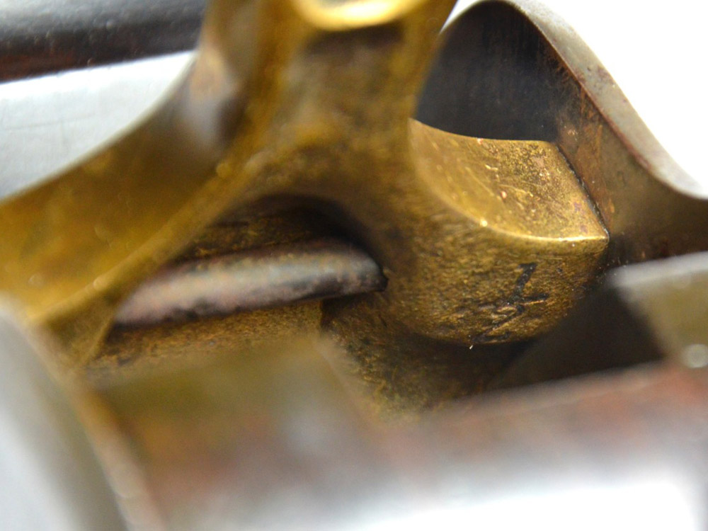
Unless otherwise specified, such as in the case of a customised order, the bedding angle for the cutting iron was usually set at 47½°. A narrow strip, or plate, of mild steel was also riveted to the inside of the body shell just behind the mouth. This helped to add mass and support to the back of the cutting iron.
Models after 1913 were sometimes fitted with an adjustment mechanism to control the depth of cut. These planes were then given a new model designation and referred to as No. A1 planes. More information on the Norris A1 Jointing and Panel planes can be found here.
Unlike the comparative Spiers models, it is unknown whether Norris offered these planes with a mahogany infill as standard in any list. I’ve certainly not seen any — except for the later cast model planes — but, as always, there are exceptions to the rule and custom orders may have been taken. If anyone out there knows the answer to this please leave a comment at the bottom of this page.


![]()